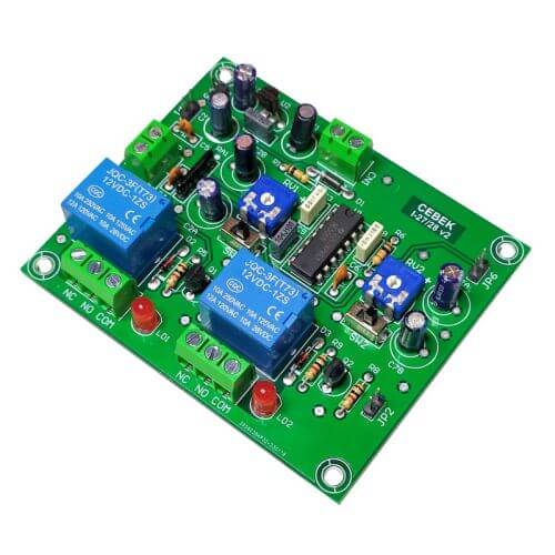

2-channel sequential delay timer relay module. Individual activation time setting from 1 to 180 seconds for each relay. Communication I/O connections to daisy chain multiple units. Mains rated relay outputs. Start and Reset switch inputs. Power-Start option.
The module can be activated by the Start Input (using for example a push button or relay contact closure) or by selecting the Power-Start mode so it activates on power up. Power-Start mode is set using a header jumper not included (Order Code JUMPER-RED).
On activation Relay 1 turns on for a user-adjustable delay period. On completion, Relay 1 turns off and Relay 2 turns on for a second user-adjustable delay period. When relay 2 turns off the unit returns to its standby state. A fresh Start Switch input is required to repeat the cycle. This can be performed manually or automatically if you connect the Start Switch input to the relay output of a cyclical timer (e.g. VM188). This setup provides automatic and continuous retriggering of the timing cycle with a user adjustable pause time provided by the cyclical timer to produce a repeating on/off/pause/on/off/pause/etc. effect.
Both delay periods are independently settable from 0.1 - 240 seconds. Scale switches select one of two delay ranges, 0.1 to 24 seconds or 1 second to 4 minutes, giving more precise and easier time setting using the onboard potentiometer (header pins allow the use of user-supplied external potentiometers if required).
This is a non-retriggerable timer - the relays will always turn off at timeout. Any further Start Input triggers received during countdown or it being in an open or closed state at timeout are ignored. The timer resets on timeout and is ready for a new trigger. The Start input must go open circuit and be closed again to register a new trigger input.
A Reset Switch input immediately stops the timing sequence, turns off the active relay and returns the module to its standby state.
Each board has a communication input and output that allows several boards to be daisy chained together.
The module has no memory function and will always start from the relay 1 position when first activated.
The module includes protection against inverse polarity, relay active LED indicators and screw terminal blocks. Requires external 12V dc power supply (Order Code 660.446UK with connector 777.001UK).
You can also use this board as a non-retriggerable double delay timer (see tab below) or to reverse the direction of a DC motor or polarity of a DC supply voltage.
2023 Product Update: New improved DIN-Rail size board with wider time range and easier setting. NB Video shows the old version of this product but application is essentially the same.
Specifications| Supply Voltage | 12V dc |
| Power Supply Options | Power Supply Module: CFE103 or UK Plug Power Supply: 660.446UK with connector 777.001UK |
| Current Consumption | 25 - 80mA max |
| Minimum Delay Time/Relay | 0.1 second |
| Maximum Delay Time/Relay | 240 seconds |
| Times Scale Ranges | Scale A: 0.1 to 24 seconds Scale B: 1 to 240 seconds |
| Output | 2 x SPDT Relays |
| Maximum Output Load | Up to 250Vac or 28Vdc @ 7 Amps max. resistive (2A inductive) (Relay Datasheet) |
| Relay Connections | NO, NC, C (Relay FAQ) |
| Reverse Polarity Protection | Yes |
| Dimensions (WxHxD) | 72 x 87 x 20mm |
| DIN-RAIL Mount | C7566 |
| Enclosure | WCAH2851 |
| Board Connections | Screw terminal blocks & header pins |
| Product Format | PRE-ASSEMBLED Electronic Module Product Format Info |


